RESOURCES.
LITERATURE
Latest research featuring Alpes Lasers’ products:
A comprehensive experimental and kinetic modeling study of 1-and 2-pentene.
S Dong et al. – Combustion and Flame, 2021
–
DI Pineda et al. – Combustion and Flame, 2020
_
Laser absorption tomography for ammonia measurement in diesel engine exhaust.
EF Nasir, ST Sanders – Applied Physics B, 2020
_
Optical frequency metrology in the bending modes region.
M Lamperti et al. – Communications Physics, 2020
FAQ
How do I handle or carry a QCL?
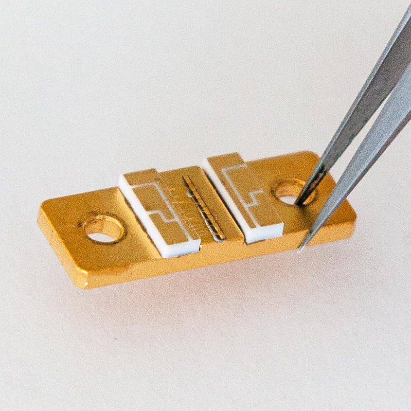
The most delicate parts of a QCL are the laser chip itself and the bonds connecting it to the ceramic pads. Therefore the QCL should be touched only at the copper carrier (far from the laser chip and the bonds), or at the ceramic pads (again away from the bonds).
To insert it into or to take it out of the Starter Kit housing, gently grab the ceramic pad from above with fine tweezers, and whenever possible, carry the QCL placed flat on a stable surface. Take special care not to touch bonds nor the laser chip itself, since this can immediately destroy the QCL. More detailed instructions can be found in §7.1 of the manual.
The two most important things to keep in mind are:
- Avoid contact of the front facet of the QCL with any object (like the walls of a box where it is stored).
- Never allow water droplets to condensate on the QCL.
What are the allowed pulse lengths for a pulsed QCL?
Pulsed QCLs are delivered with a datasheet. Typically, lasers are tested using 50 ns pulse lengths. If you wish to use shorter pulses, you can do so and the laser will react as shown on the datasheet, with the average power being accordingly lower at a fixed repetition rate. The shortest pulse length achievable with a LDD driver is 22 ns.
Longer pulse lengths will heat up the laser and cause chirp within the pulse and a decrease in peak power. If you intend to use longer pulse length, this should be specified at the time of purchase. A special datasheet can be produced.
Using a laser with pulsed lengths longer than specified in the datasheet is liable to void the warranty.
If you wish to take the risk, a good method is to use a fast detector (e.g. a MCT detector) and slowly increase the pulse length. The maximum workable pulse length will be the length at which the instantaneous power at the end of the pulse is 50% of the power at the beginning.
What are the allowed pulse lengths for a CW QCL?
A CW QCL is tested only with continuous excitation, where any pulse longer than one millisecond is seen as “continuous”. The performances shown on the datasheet are the performance in the steady state and do not consider transient effects that occur in this first millisecond. It is also possible to use pulsed excitations of any shorter length on these lasers bearing in mind that:
- The wavelength at the beginning of the peak will be shorter than the CW wavelength
- The signal will show chirp
- The strength of the chirp can vary from one laser to another
- There is no guarantee that the laser is single-mode with short pulses
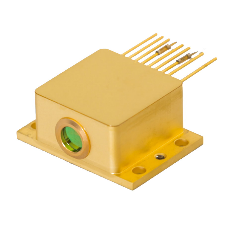
What is the distance from the laser facet to the ZnSe window in a LLH?
The window thickness is 2.0 +/- 0.1 mm. The laser facet is 4.5 +/- 0.5 mm from the exterior facet of the window and 2.5 mm +/- 0.5 mm from the inside facet. The window is 1.0 +/- 0.2 mm recessed from the front of the LLH.
How can I read the voltage output of the laser from the connection 5 and 6 of the LLH?
What is the linewidth / frequency noise of a QCL?
The instantaneous linewidth of a QCL can be extremely low, of the order of kHz.
In practice however, the total noise of a system will almost always be given by the noise of the current driver and/or the temperature noise, and when that noise is much higher than the intrinsic noise you can consider the QCL as a perfect transducer and compute the effective amplitude or spectral noise from the datasheet.
Do QCLs suffer from optical feedback?
What type of chiller should be used to cool the LLH?
That being said, using a flow rate of 0.3 l/min of water kept at a temperature in the 15°C-20°C range should be sufficient for most practical purposes.
What type of cooling is needed for the HHL?
There are two sources of heat in a HHL: the heat created by the laser itself, which can be read from the datasheet, and the heat created by the TEC which is equal to its power consumption and depends on the temperature differential between the laser chip and the baseplate of the HHL. The sum of these can reach up to 40W and must be dissipated away from the baseplate. Typical specifications require the baseplate to be kept at a temperature of 20°C.
While it is in every case required to connect the baseplate to a heat sink, different types of heatsinking methods can be used, from passive cooling to air cooling to water cooling. The HHL is designed to allow maximum flexibility in your system design by providing a minimal flat interface.
It should be noted, however, that only the bottom baseplate is directly heated and designed to be connected to the heat sink. It is not recommended nor useful to attach anything to the top plate of the HHL.
Can I solder a laser submount?
To protect the coatings on the lasers and avoid melting the indium solder used on some submounts, it is not recommended to heat the submounts to temperatures higher than 100°C, even temporarily.
I cannot connect the S-2 driver using the supplied software
The supplied control software is not fully a driver but a control panel that allows you to access the hardware. Access to this hardware must be allowed by your computer system in order to use it. Such access may depend on your particular system and Alpes cannot guarantee the correct working of your computer. Nevertheless, if you cannot see or use the ports you can follow these general guidelines:
- Is the red LED light on the board (visible if you use the OEM version without protective box) lit? If it is not, check the power connection.
- If you use the USB-to-serial adapter, while normally this device is automatically recognized by most distributions it could be not yet installed on your machine. You can download the drivers at http://www.ftdichip.com/Drivers/VCP.htm; follow the instructions on the site.
- Under linux if libraries are missing installing libxcb-xinerama0 (through apt-get) should help
- If you can see the correct port but the connect button does not work, you may not have access to the port. Launching the software with admin rights (i.e. using sudo under linux) may help.
Why is the datasheet of the laser different from the one I picked from the website?
The datasheets shown on the website are measurements taken on submounts. When the laser is encapsulated, the submount is soldered directly onto the thermoelectric cooler, sometimes improving thermal performance. A new measurement is taken immediately prior to shipment with the final performance.
